

 Reply With Quote
Oh yes, can't wait to see the finished product that piece of wood is beautiful.


Still following here. I am visioning more stockmakers and competition. Prices falling. Ok back to earth!
Oh yes, can't wait to see the finished product that piece of wood is beautiful.

Im enjoying this very much! Im a complete DIYer and builder. Avid gunsmith & builder, I make custom knives and build tools like my 2x72 belt grinder. Im also 100% disabled and have only one arm/hand to use, so building and following others gives me a great deal of confidence. I am a HUGE fan of watching others go through a big project, and the pictures and subsequent stories are wonderful! So Ill say to the OP, thank you very much for sharing this with us.
It is a very special thing to build something on your own. Anything, whether it be a tool, part or machinery...gives one an amaizingly fulfilling sense of accomplishment. It brings a healthy pride that can be shared with, and even help others in their own life. Again I say thank you, and keep it up!
I really like these sorts of posts. I just wish I had more disposable income to invest, I’m slightly jealous. Someday. . .
I appreciate you sharing your story. I am just beginning to consider making my own knives. I need a belt sander and Im considering making my own. Would you mind posting a picture. Id love to see it. Maybe start a thread and share some knives too.Originally Posted by Dave Hoback

Thanks!
Sent from my iPad using Tapatalk
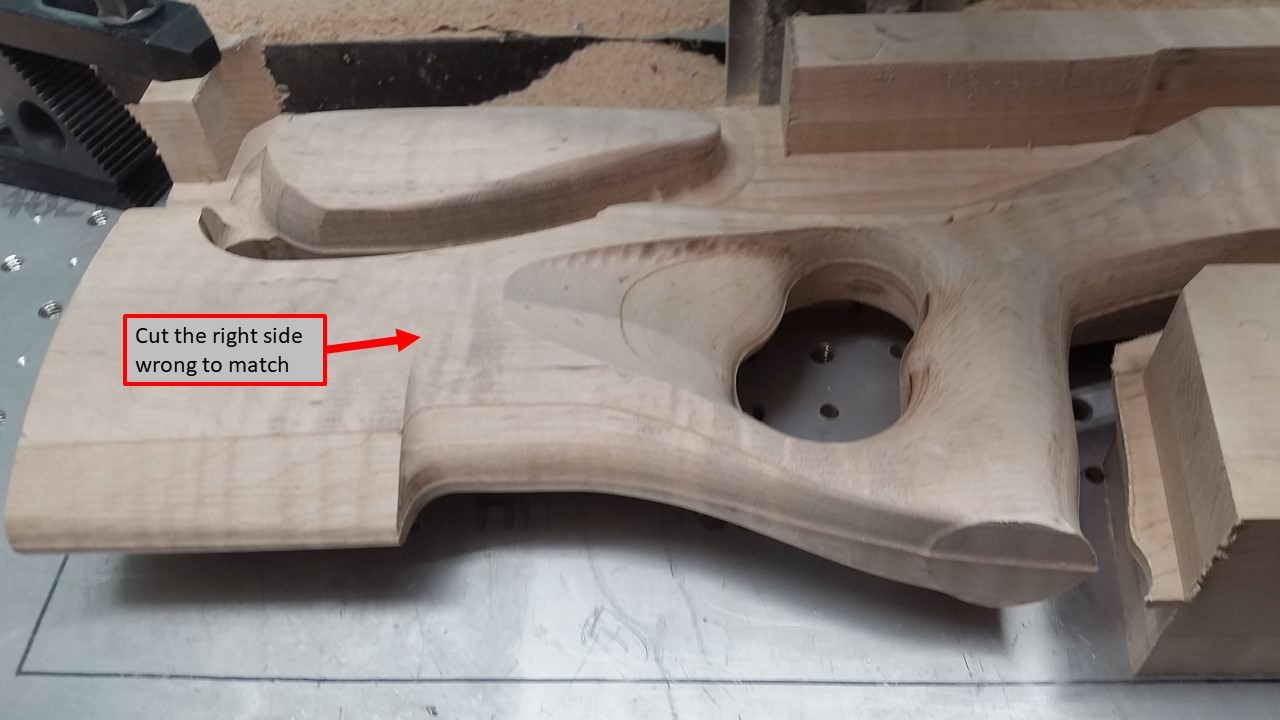
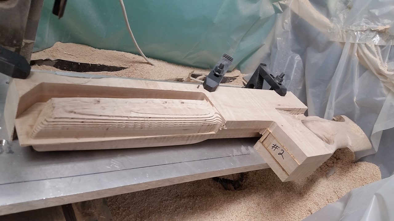
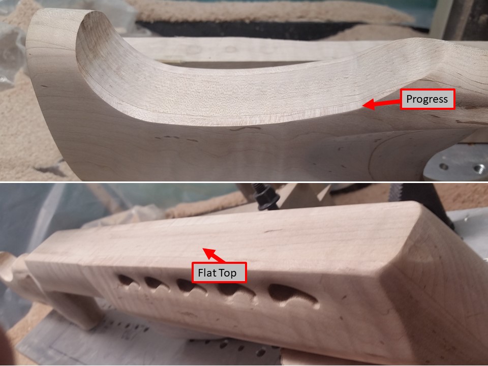
Progress continues:
I have ALMOST completed the right side of the stock.
You can see in the picture below that it is very close to finished. 'half-finished'.
However, this wouldn't be the my kind of project unless I made it more difficult than it should be.
The CAD model was actually completed ~3 years ago. My CAD skills were lesser then, so my friend (220-Swift stock mentioned earlier) did the CAD work.
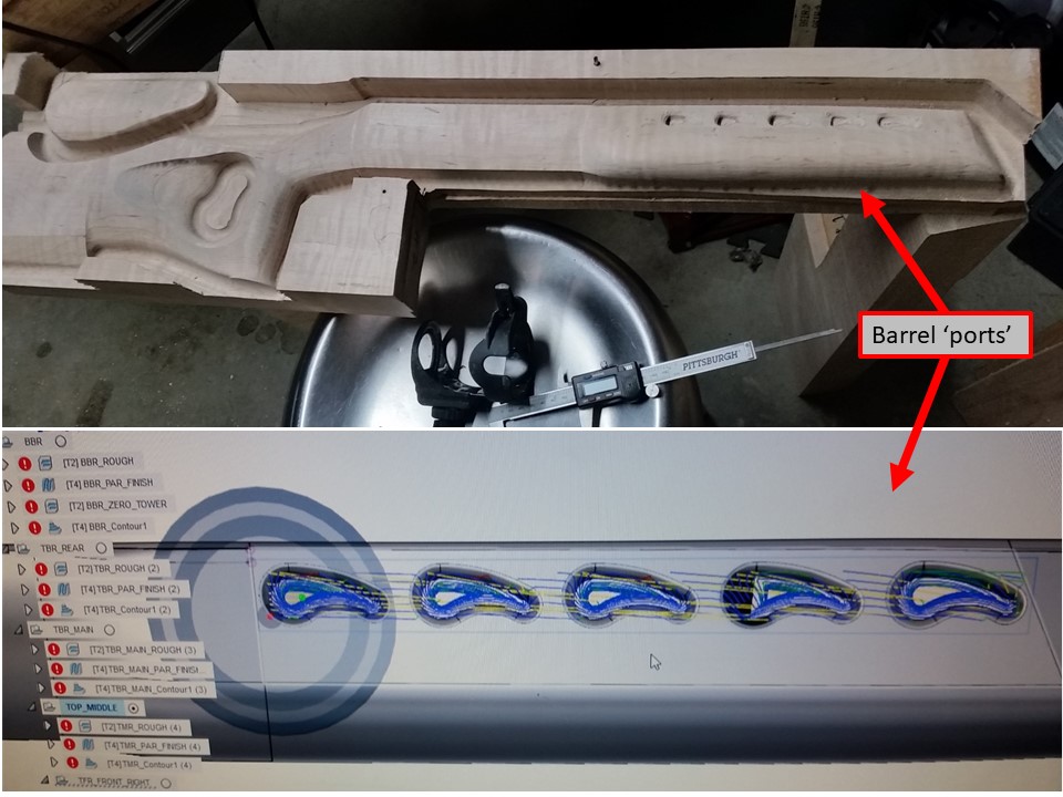
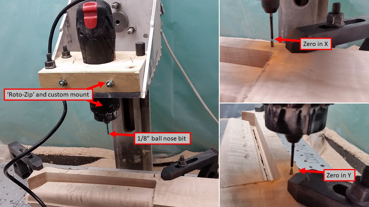
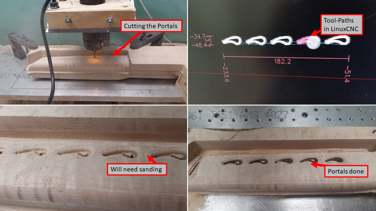
We decided that we could get an 1/8" bit into these front barrel ports. They are purely cosmetic...but were included in the design and shaped and sized for specific reasons.
Well...now that I am actually cutting the thing out, I am realizing that I do not have any 1/8" router bits.
I do have 1/8" 2-flute carbide ball nose end-mills. These would work, but I cant hold an 1/8 inch tool in a 1/4" router collet.
Out in the garage, I happen to have the Roto-Zip that I borrowed from my FIL about 2 years ago. And...it takes 1/8" bits.
All I need to do is attach the Roto-Zip to the CNC machine...
So, I'll just whip up another clamp mount - measure, CAD, CAM, run code...
Couple minutes later...
I have another 'spindle' in another mount. (There may have been some belt sander work for final perfect fit)
Portal CAM G-code made and run:
And now we have a finished Right Side!
(I am now happy...and nervous)
Im happy and excited to continue watching your build progress.
Your happy & nervous...what's to be nervous about? My dad would say; "now don't screw it up!" And of course I usually did!! Just kidding....Looks great so far.
Carry on
Just curious.....how many lines of code is in this process?
"As long as there's lead in the air....there's still hope.."
The roughing operation for the Front Right side is 1,624 lines of G-Code.
The Parallel Finish operation is 2,051 lines.
The Contour Finish is 4,259 lines.
The 1/8 Ball work in the portals is 10,403
Yes, I am making progress on this project.
Yes, it is slower than I would like.
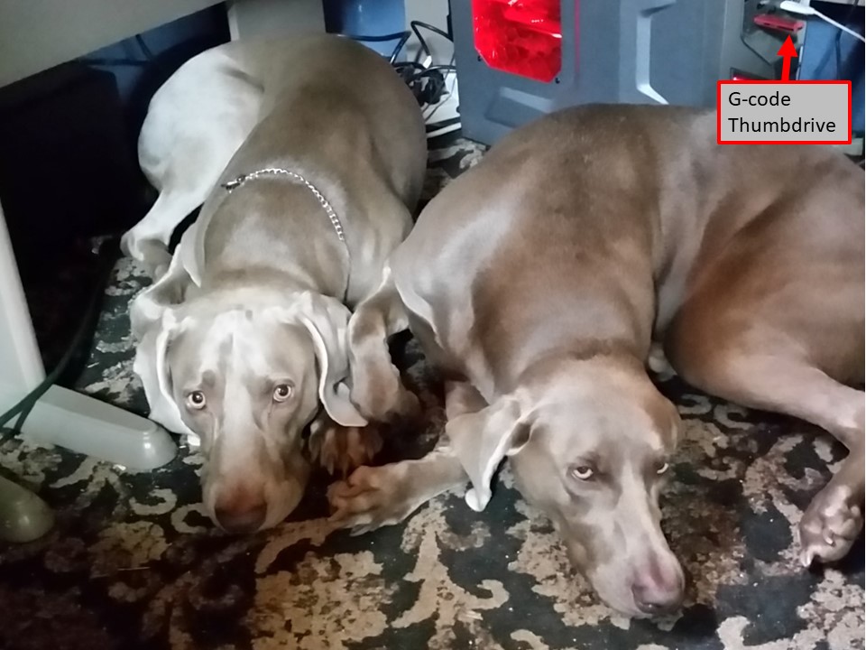
Yes, occasionally its because I have Weims under my desk and I cant get to my thumbdrive.
They want to be nearby at all times. Even if that means getting their ears caught under the desk chair. I try to avoid that. They look at me like its my fault.
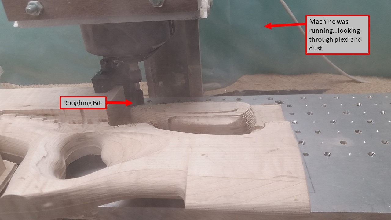
I have started cutting on the left side of the stock.
Setting up for these cuts had to be thought about back during the first cuts.
Once you cut a flat and square object into a rounded and curved object...you start to have trouble aligning things perfectly.
This is the case here. I needed to be able to flip the Stock Blank over and have it sit flat and square on the CNC table.
I also needed to be able to clamp the Blank down and have it held securely.
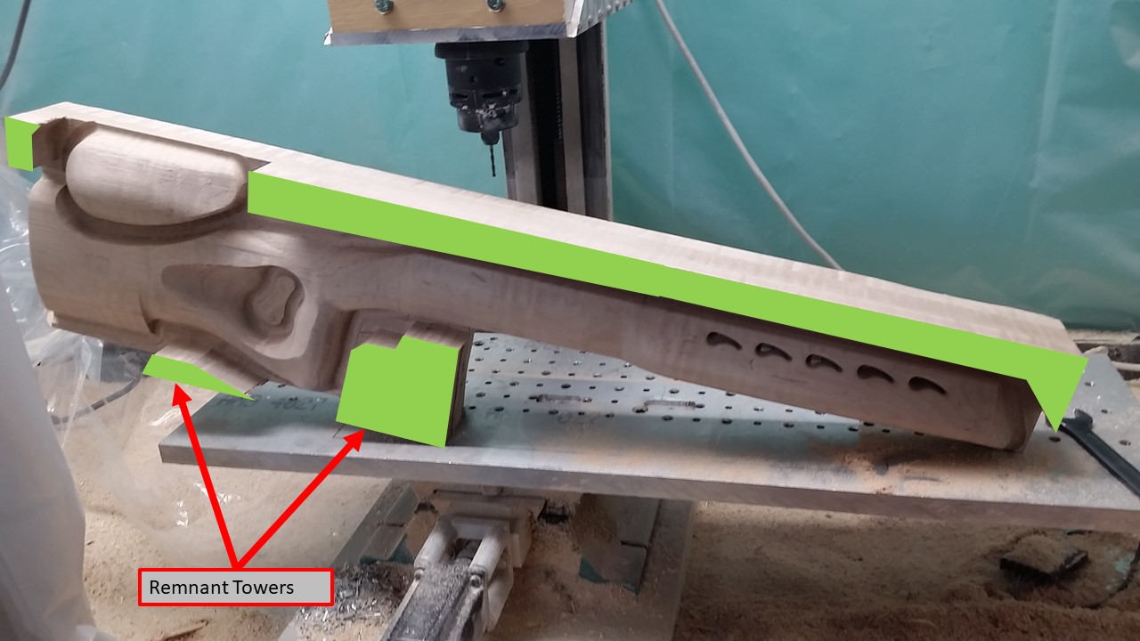
SO...when I was cutting the right side, I instructed the CAM to only cut the actual stock.
I built restriction zones in areas that I knew would make decent 'remnant towers' for the stock to sit on when I flipped it over.
These remnant towers are necessary so that the top surface of the Left-Side is flat and so that I can clamp the Stock Blank to the CNC table with some force.
The right side of the stock is now curved and shaped...and doesnt touch the CNC table.
In addition, I need to be able to clamp the Stock Blank...while also keeping the clamps out of the area that I am about to cut.
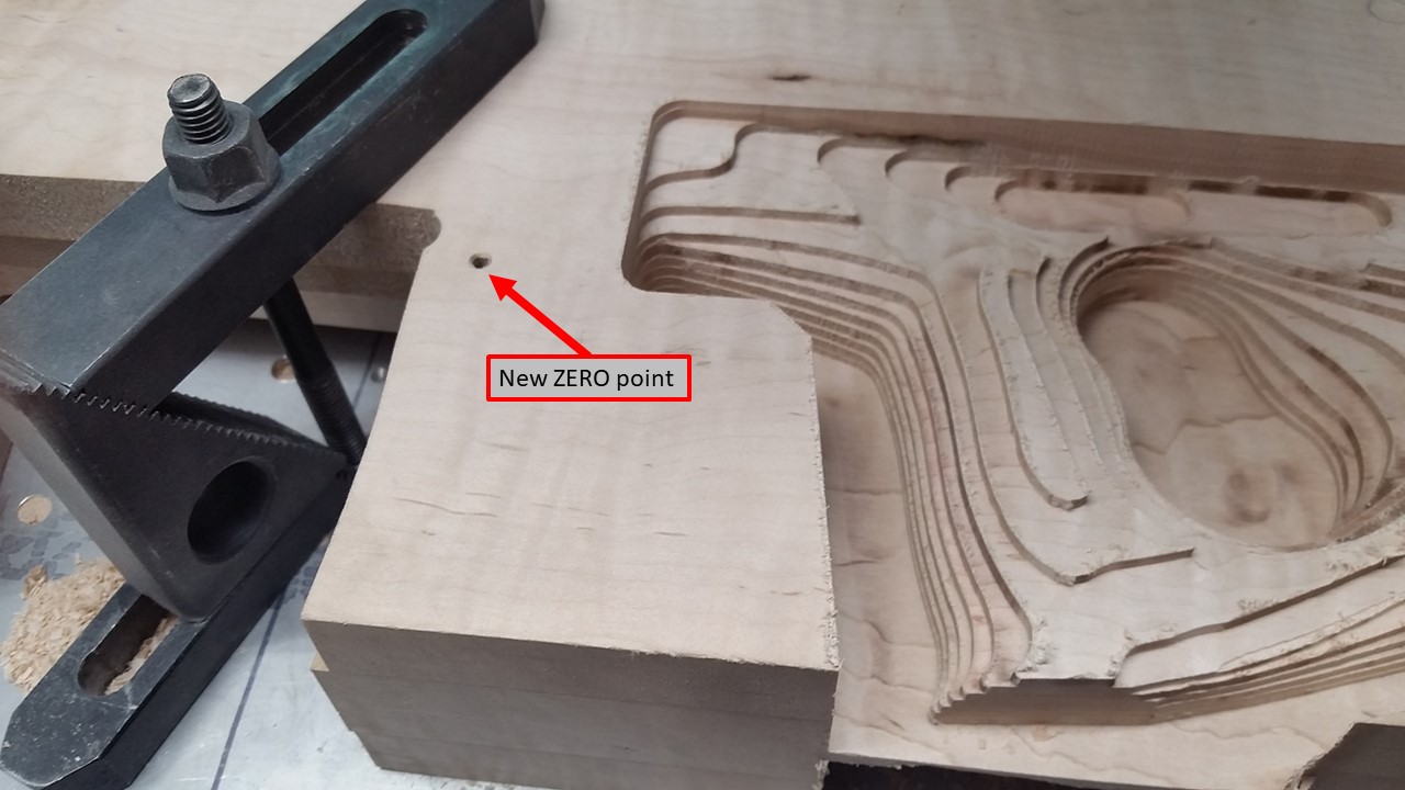
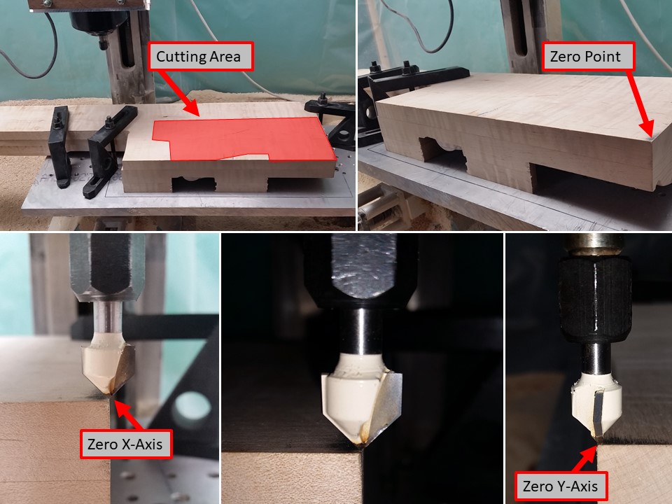
After aligning the Blank with a thousandths Dial Indicator (not shown)...I can Zero the machine on the back bottom corner of the stock blank...which was cut square and flush back in the wood shop 3 years ago.
One of these days, I'll get a touch off tool that fits a 1/4" collet.
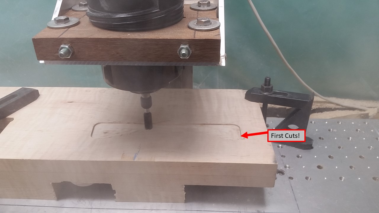
I started the cuts on the Left-Side.
This is a nerve wracking thing...because each new step involves the risk of mistakes or mechanical failures that could ruin all the work so far.
Also, this is the Roughing operation that will remove the back bottom corner - which is used as the zero point for this operation.
Once you hit go on this portion - there is no going back.
I usually stand and watch the machine or go to the other side of the basement to my desk to prep the next batch of code.
While doing the CAM work for the finishing operations, I could hear the Router working harder than it should be.
It just didn't sound right. I stopped the CNC machine during the next clear moment (when it is moving to the next area to cut).
Upon closer inspection, it seems the Router Bit had begun to walk out of the collet...making the cuts deeper than they should be. This explained the router bogging down...
I noted the line of code that the machine was currently on so that I could return to that point.
I moved the table manually and reset the bit height. Technically, I loosened the collet and used the Z-axis to push the bit back in to where it was supposed to be - then tightened the collet.
I resumed the operation from where it left off and let it finish.
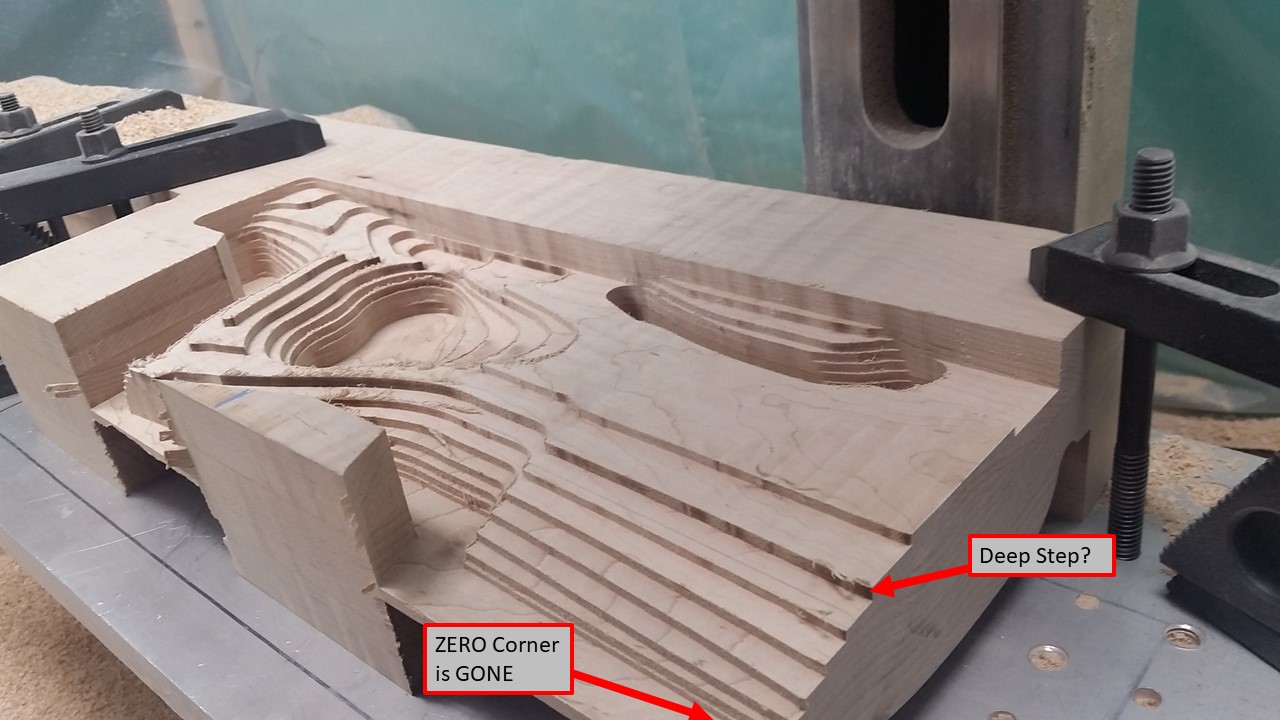
Also of note in the picture above is the missing Back Bottom Corner - which is used for the X and Y zero point for this operation.
I inspected the work from the roughing operation. The CAM is set up such that there is material left for the finishing bits to remove...hopefully the bit that walked out didnt cut deep enough to get into that margin of error.
Finally - I used this setup to mark a new ZERO-Point for future Ops.
This came in quite handy...
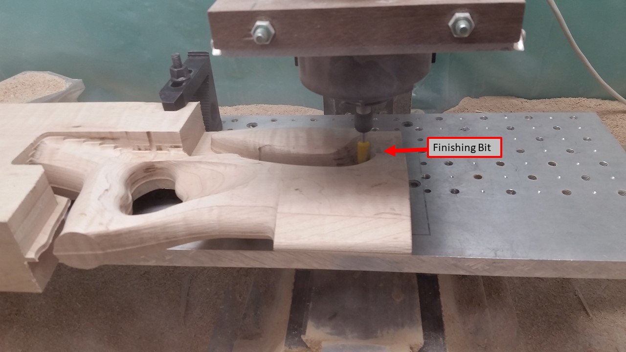
I had prepped the finishing passes for this section.
When I changed bits to the round one for finishing and re-zero'd the Z-axis...the CNC control computer shut off.
I have been having issues with the hard-drive in it for a few years. Maybe at some point I'll get to fixing the issue.
Regardless, as it was late, I left the machine in this state and decided to tackle some more on another day.
This stock project is kinda complex.
I just learned...I learned not make assumptions.
Since the CNC machine turned off...I have to turn it back on (of course)...and then re-home each of the axis and then re-zero each onto the part.
Well, since I cut the old zero-point away, I have to use the 'new' zero point that I made.
(this seems obvious - whats the point?)
In the CAM setup, I establish a zero point. I then have to use the CNC machine to 'touch-off' on that exact point in order for the machine to know where it is, and make all the cuts where they are supposed to be. With MOST of my touch off settings, that point is at zero-X, zero-Y, and zero-Z.
I figured that I could just use the 'new' zero point and just tell the CNC machine that it was 'over there'.
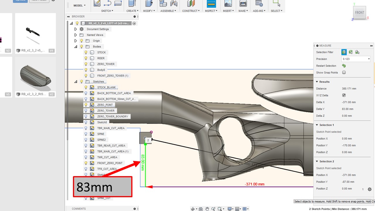
The settings were supposed to be -371 in X...and +83 in Y.
Somehow, I walked over to the machine and told it -371-X and then +87 in Y.
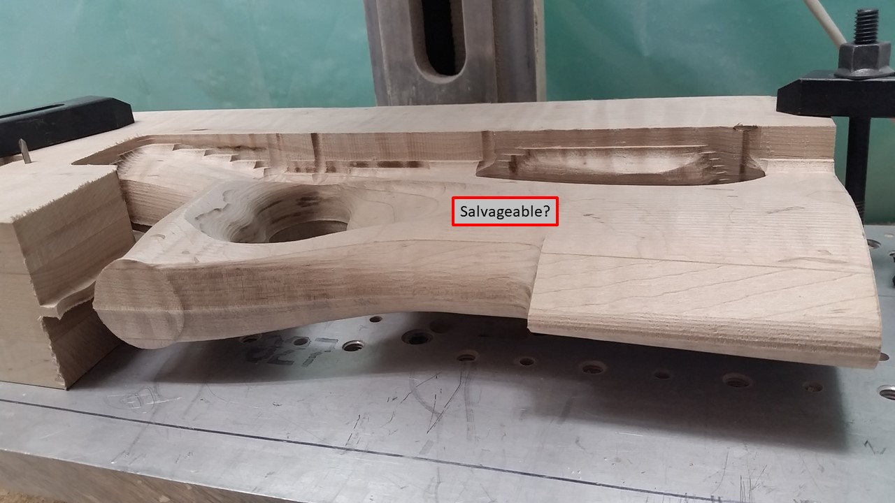
This mistake did actually cause some problems. However, I talked to my wife about it (the stock is for her) and she said that I should see what I could do to salvage the effort so far.
I reset the Zero to 83mm. Re-ran the finish passes on this section.
I actually flipped the stock BACK over and ran the code on the already finished right side...with a 4mm offset. If this stock is going to have some things out of whack...I at least want the errors to match on both sides.
I think you have a good handle on things, and I would continue the project!
Next Section.
Upper Back Left...
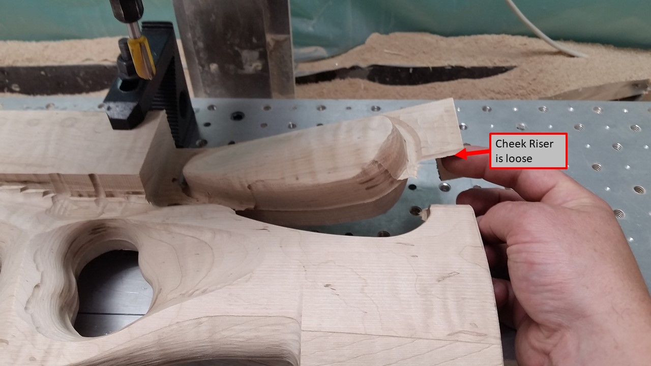
In this case I restricted the operation to just cut around the cheek riser.
The idea would be that I need to leave the Stock I am cutting out attached to the Stock Blank...since the Blank is the only thing being held to the CNC machine.
I would like the areas that I leave attached to be pretty flat and easy to clean up with a belt sander or some other power method.
The finishing pass actually cuts through to the other side and 'releases' the part from the blank.
I stopped the finishing pass JUST as it was finishing and before it had completely 'released' the cheek riser. There was just a small portion still attached. This was easily bent and cracked apart.
There it is...cheek riser is 'done'.
The basic shape is there...and it has the details from the model very well defined. There will be some sanding to remove the flakes and whatnot.

Slow and Steady Progress.
I decided to cut out the front of the stock and leave the middle portion for last.
In order to cut the front, I need to establish yet another zero-point...precisely measured from the last one...which was precisely measured from the back bottom corner of the Stock Blank.
In order to establish that zero-point, I actually had to position the stock on the machine, align it using a dial indicator, clamp it down, touch off the old zero-point and then move the bit to the new point.
I think I learned my lesson, and I will be checking and double checking all my measurements in CAD and CAM and on the machine itself.
After making the 'new' zero-point for the front section, I again repositioned the stock, aligned with dial indicator and clamped down...using only locations that would NOT be hit by the bit.
After that, its only a matter of letting the machine run and hoping nothing breaks.
The router was sounding a bit labored...either the roughing bit is getting dull...or I have some other problem cropping up.
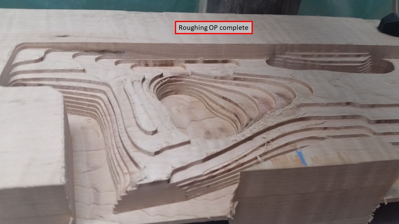
And....Front Section Roughed Out!!!!
Thanks for sharing. Waiting on next posts
I see a plan coming together!
Nice work.
More Progress...more challenges. Such is life :)
I started the finishing passes on the Front Section of the Left side...which is where I left off.
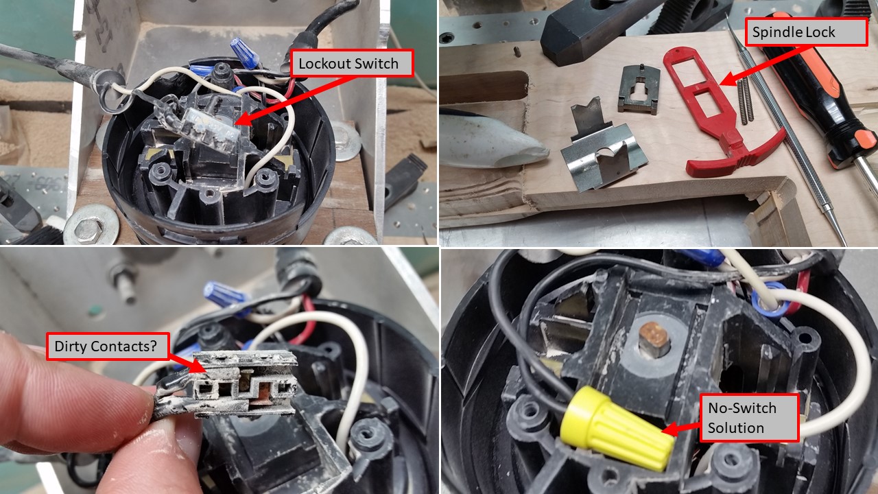
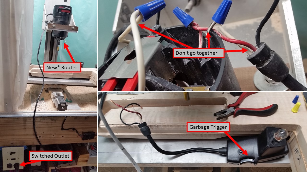
Things seemed fine and going smoothly...when the New* Router died. This is bad.
The CNC machine is still moving the stock around, but the router isnt cutting anything.
I was sitting at my computer not far away prepping the next batch of code...quickly ran over and stopped the CNC machine from moving.
FORTUNATELY,the router stopped on the finishing pass. It wasn't cutting much...just a 1mm deep parallel cut.
I tried to restart the router, but it wouldn't stay running for more than 30 seconds. This is a major wrench in the gears.
Not that I want to...but it seems its time to take this thing apart and figure out why it doesn't like me.
The first thing I tried was the spindle lockout switch. Its little, and it didnt look like it was getting pushed all the way to close the switch when the spindle lock was disengaged.
I took the switch apart, cleaned it...and then just decided to hard wire. The Old* Router didnt even have one of these...whats the worst that can happen :)
Still...no-go. Router wouldn't stay running for more than a few seconds.
NEXT, I tore apart the trigger switch. Thing was filthy and pitted.
From what I read in some router forums, triggers fail pretty often. One of the things you can do is rotate the sliding contact piece so that the fresh side is now contacting the stationary contact. I cleaned out the switch and turned the moving contact piece 180.
Router wouldn't even spin.
Chatting with a savvy woodworker - he suggested the router brushes.
They are pretty easy to get to, so I yanked them out.
They were actually in great shape, and seemed to have plenty of material left.
However, the contact plate' that they each sit on was slightly pitted. I sanded this down a bit to expose fresh contact surface and put the whole thing back together.
NOTHING. not a whisper, not a hum...ZIP.
If I wasn't a disorganized mess, I would locate my multi-meter and do some checking...where is the juice stopping.
Instead, I decided to just try hard-wiring the trigger switch out of the equation...as I had already by-passed the spindle lockout switch. Process of Elimination, right?
(BTW, I also learned which wires in the trigger switch do what. some go together...some dont)
BINGO. found it. fixed it. running router!
Its actually kinda better. I can now start and stop the router from outside the enclosure. I dont have to open the 'sliding door' to turn off the spinning router. Its nice.
Turn on router, start CNC machine moving in the right direction. let it cut and voila.
Front section almost done (still have to swap out the router for the Roto-Zip and cut in the portals.
Progress. slow and sometimes painful...but, progress.
So much left to do...
I swapped out the big New* Router for the 'roto-zip'. I had already made the mount for it while working on the other side of the stock, so this only took minutes...instead of an hour.
I prefer to zero the roto-zip bit while it is spinning. Somehow, as I am setting my X and Y axis to zero directly over top of a little point, I find it visually more consistent when the bit is spinning.
Touch off Z axis...load the code...and away it goes.
The setting that I have for the little bit obviously are slightly different than for the larger bits...it leaves little scallops in the surface that I don't get with the larger 1/2" round nose bit.
Still, there is no way for me to cut in those small portals without this method. Nothing some 120-grit sandpaper can't blend, right?
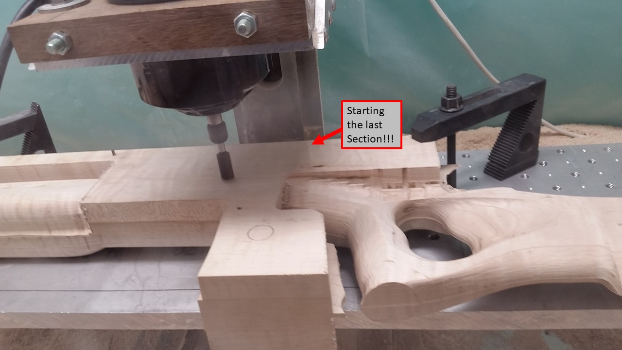
With that done, I have nothing left but the LAST section. The Middle of the Left Side.
I actually took a picture of this when it was set up and the bit was about to touch the wood...kinda as a moment of celebration and trepidation.
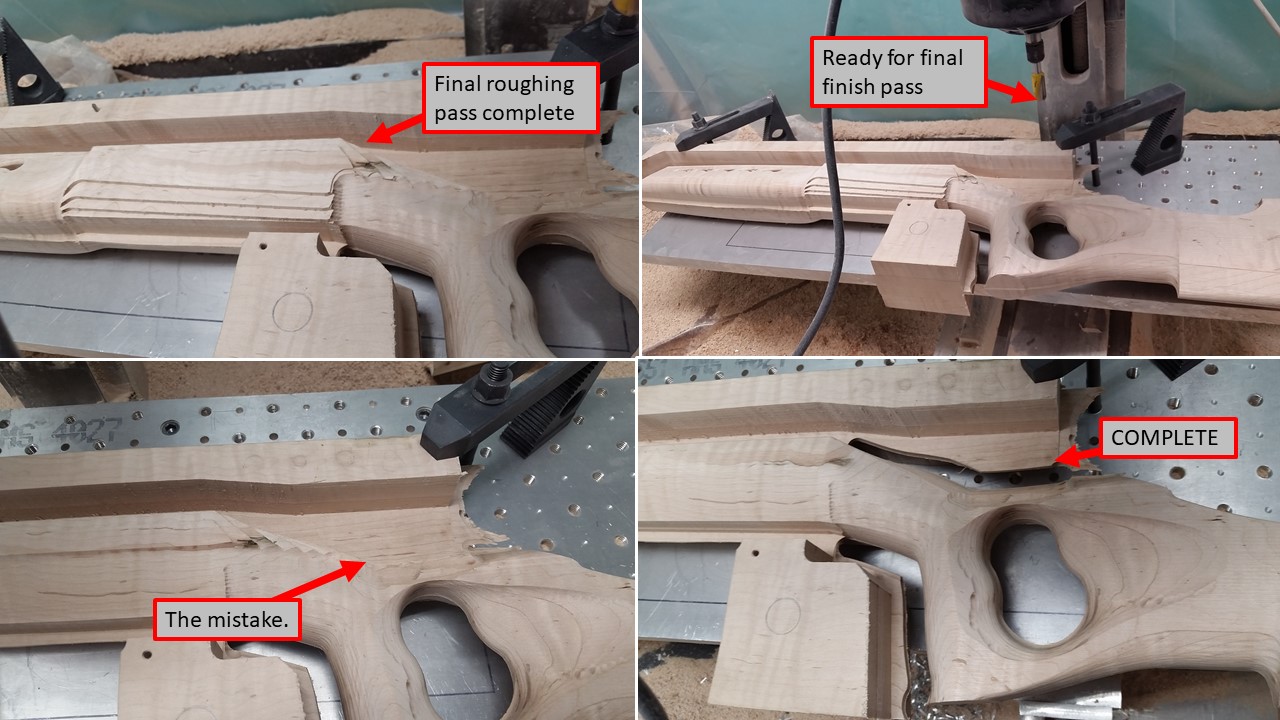
Roughing pass completed.
Finishing pass started...
I run 2 different finishing operations...
One is just X-axis parallel...back and forth over the flatter sections.
The second is a contour following operation that steps its way down along the steeper sections.
It was just after the parallel operation had started...I was prepping the code for the contour operation when I realized something didn't look right in my code.
There are enough other glitches...this one isn't major. I'm not even going to really describe it. Suffice to say that the area of the stock behind the tang will have to be 'blended'...as the right side and left side don't perfectly match.
And...
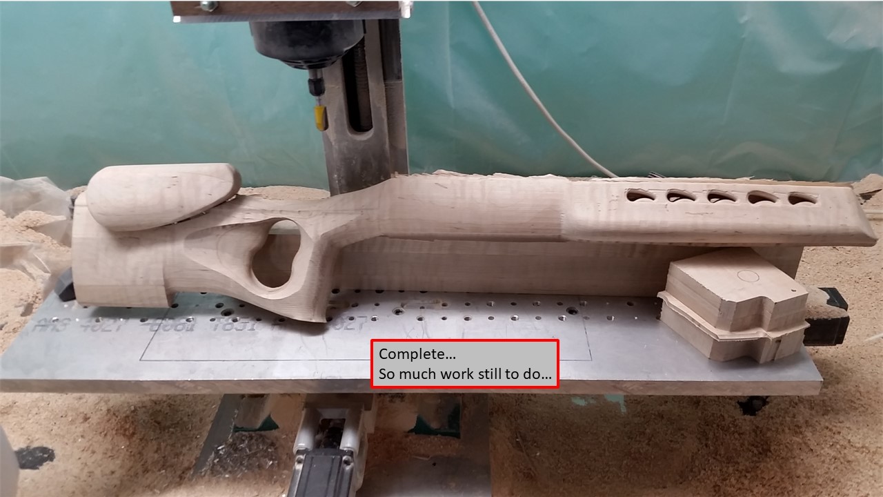
Its done.
The CNC portion of this project is done.
It is 'mostly' done.
I still have to do the inletting for the barreled action (which still isn't barreled)...
and for the bottom metal...which was only just ordered.
So much left to do...so much already done.
Very nice!
Will you write another program for the rough inlet?
Wow
Yes. I am currently doing the measuring and CAD for the action inlet and the bottom metal inlet. Those will then be turned into code for the CNC machine to run and cut.
This give me a few more opportunities to make mistakes...but, if I do it right, I also get the opportunity to have the machine do real nice work.
Bonus - I'll have the inlet CAD and CAM should I ever want to make another one.
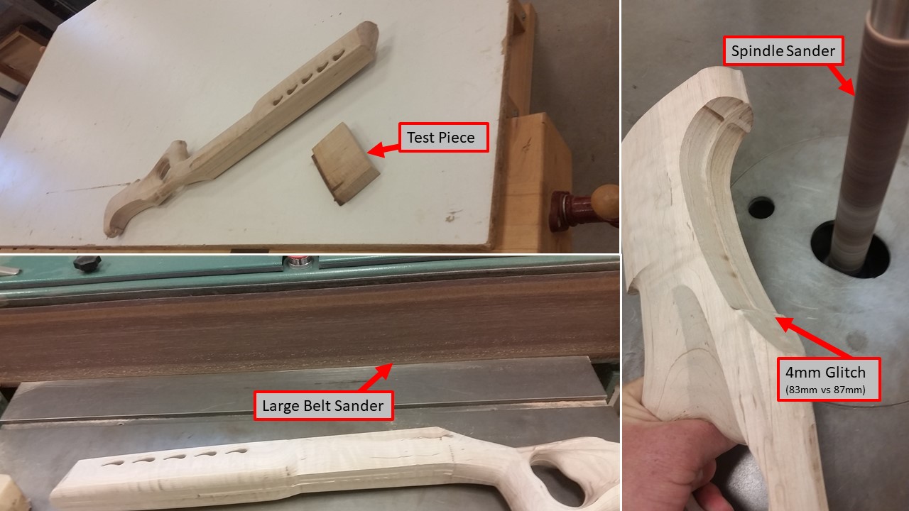
I have access to some pretty awesome tools. I took the stock as cut...and brought it back to the wood working shop.
There, I get to use a clean work-bench (I really need to be a neater person).
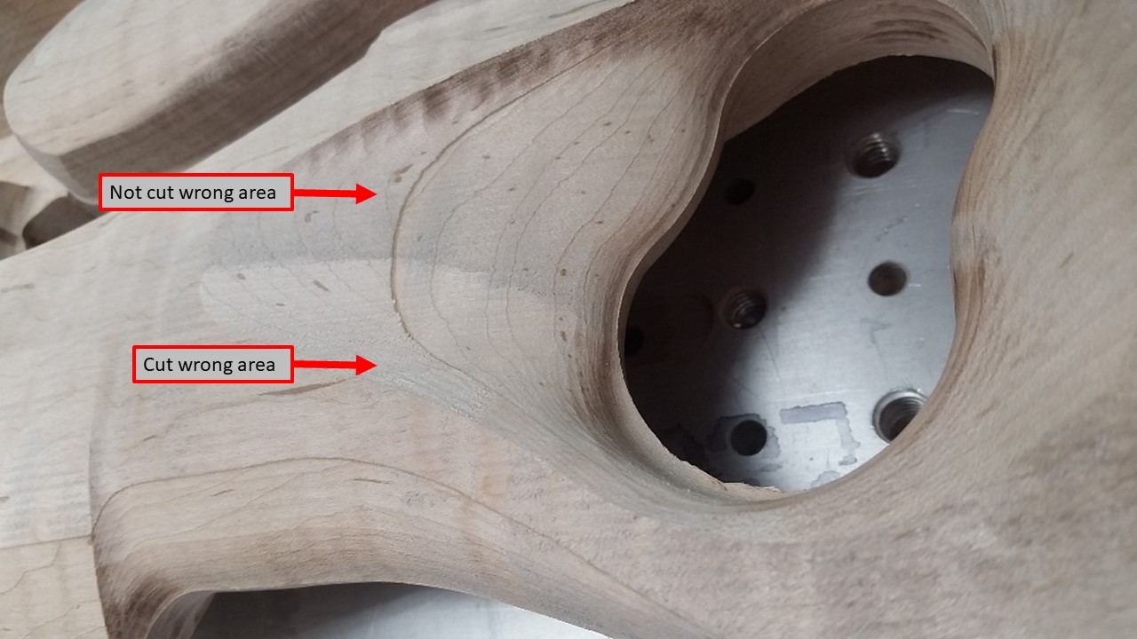
I used the spindle sander to work in some of the tough areas. The Cutout for the cheek riser suffered a little from my earlier mental glitch. 87mm is not 83mm.
I was able to do some decent work with that spindle sander and really make some improvements. There is still some work to do in this area.
I also used the large flat belt sander to work on the top...where the barrel channel will be.
This only needs to be flat so that I can ensure my later setup on the CNC machine is level/flat.
I'll run the dial indicator along the flat section and make sure the stock is clamped in the vice with no 'tilt'
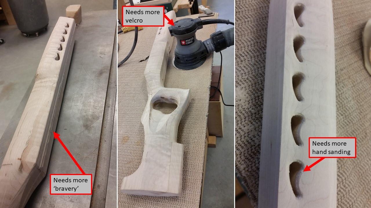
I also did some work both hand sanding and with a random orbital. The orbital had seen better days...or at least the velcro on the bottom had. Still...progress.
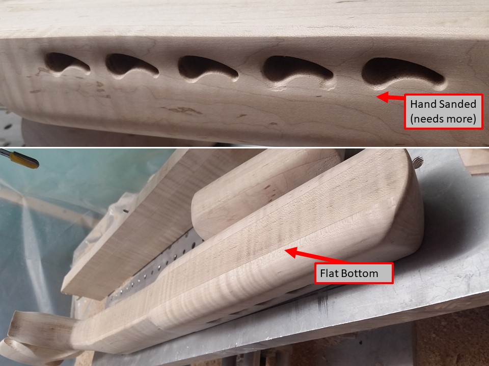
I really worked on the portals. Those things were rough when they came off the machine. If you bother to scroll up to compare, you can see what they looked like and where they are after only ~10 minutes of 120-grit. Bit of an arm workout but nice results.
I also hit the bottom with the spindle sander and flat belt sander. There will be an Anschutz rail and PTG bottom metal inlet.
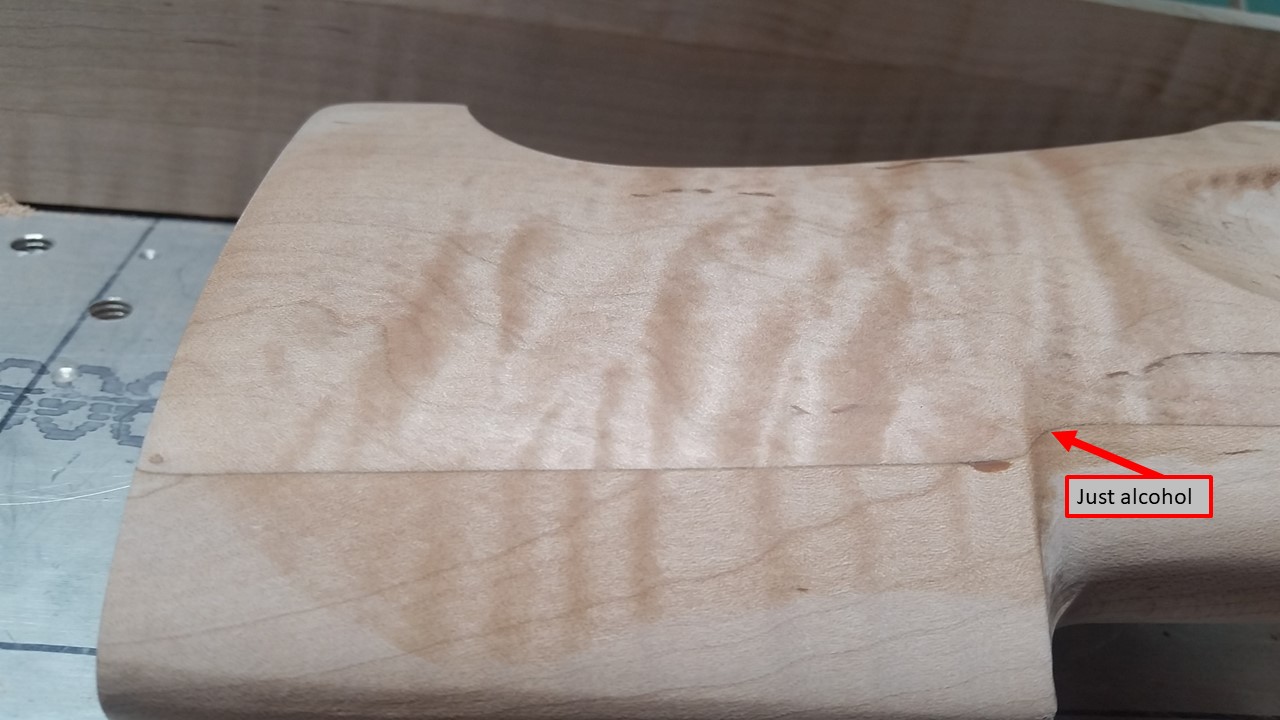
I have done a bit of hand sanding at home also. some areas are up to 400-grit. These really sow the tiger stripes when wet-down with alcohol.
Lastly...
I am doing some test work with the dyes that will be used to really lend the maple figuring some pop.
This is a personal preference thing. Some folks might hate it...others may actually like it.
The rifle is for my wife...and she is getting pretty full finishing say-so. Of course - caveated that it has to be something I can actually accomplish.
(wait...Ive never really done any of this before so it is all a guess)
The dye process is completely new to me. I have done stains on things like Oak...and I usually get told to just stop and use paint.
I dont know how the guitar finishers do it, but I am going to try to get to a finish that brings out the amazing stripes and depth in this stock.
Again...learning / testing process.
 Posting Permissions


Bookmarks